RSS

Monthly Archives: May 2012

Tile Driver

While the drywall elsewhere in the house was being primed and refined, preparations were underway in the two upstairs bathrooms for tiling that would commence the last week in May.

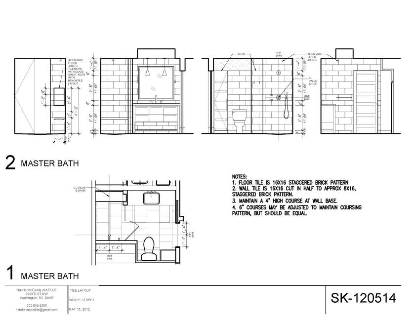
The master bath and guest bath both would use natural stone, and the original plan was to do the same oversize (8″ x 16″) brick pattern in both. The only difference would be the stone itself. The original tile design for the two bathrooms is shown below.

As we got closer to T-Day, and actual ceiling heights were established after drywall was installed, we revisited this design with our new architect. The refined version established a the following pattern, from floor to ceiling:

  • 4″ base course
  • Four full, 8″ courses
  • 4″ belt course
  • Four full, 8″ courses
  • 4″ belt course
  • Two full, 8″ courses

In the words of the architect, “This makes the layout look balanced and purposeful – since it aligns with other elements in the room and follows the tripartite rule – establishing a base, middle & top.” Hey, we’re all about purposefulness, and anything that adheres to established architectural rules instead of creating anew jibes with our pronounced anal retentive natures, so this was our new tile plan, which is shown below

The updated master bathroom tile design is below:

The guest bathroom tile design features a dark stone floor (with 4″ base up the wall) and lighter wall tile:

Back in the master bath, backerboard has gone in as a tile substrate. The long drain system and Kerdi waterproofing system boxes are to the right, ready for deployment.

Backerboard has been installed on the shower walls, below. Note the step down from the bathroom floor to the shower floor. This was the result of the use of 2×8 framing under the showers, versus the 2×10 joists everywhere else. This supports the curbless shower approach – the drain will be at the bottom, but the tile will slope upward from the middle to the step on the left and to the same level on the right, against the wall.

Here, the Kerdi system and long, rectangular drain have been installed in the master bath:

The same has been done in the guest bath, but at this point, work has progressed further, and one of the several layers of waterproofing has been applied. It’s a very subtle color; you can hardly make it out.

In the meantime, crates of tile have arrived, and are now stowed in the basement:

Here’s the tile for the master bath – Crema Ella. Lis wanted a spa feel, with tan stone. We considered travertine (a limestone), but learned that the porous nature required a lot of upkeep and would also show where epoxy or other filler had been added to fill the holes that naturally occur. The Crema Ella is a marble with a really homogenous appearance and very little veining. We totally dig it.

We’ve got a crapload of Crema Ella, eh?

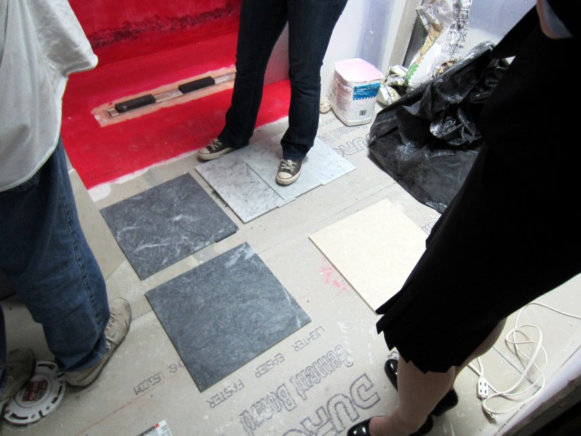
Upstairs in the master bath (all lit by the skylight, which is exceeding our expectations), we met with Natalie, our architect, Mario the CG’s tiler, and Dave to review joint size and grout color. You can see the little grout samples placed along the side of the tiles, as well as the Crayola-style box of them over to the left.

The Crema Ella is at bottom right. The other two are the floor and wall tile for the guest bath, which will have a turn-of-the-century feel to it, including the fixtures (I think we’re going to market it later as part of the Wolfe Streete Sanitarium of Olde Towne). The dark marble is Blu Masaccio and the white marble is pretty standard Goia Venatino. Part of the grout discussion was whether we wanted to highlight the pattern in the guest room (using dark gray grout) or highlight the stone (using a very light gray grout).

During the discussions, and based on the decision to do very tight joints in the master bath, the tile design was changed again, essentially to the original design of even courses throughout. The final(?) plan appears below:

In the guest bath, we talked over some additional ways to bring visual interest to the space, and have decided to do several courses up to the vanity height with the 16″ x16″ stone, then a 4″ belt course, then the 8″ x16″ brick pattern, as shown below.

Stay tuned – it’s all conceptual at this point. The GC now needs to execute on the final design.

 
2 Comments

Posted by on May 28, 2012 in Bathrooms


High and Dry(wall)

After the last of the insulation was installed, a horde of drywallers descended upon the house and worked non-stop for 5 days, completely transforming the feel of the house. We’ve been used to seeing the house in the context of exposed framing for a few months, so this step in the renovation had a dramatic impact.

Here’s a couple of photos about two-thirds of the way through initial installation in the master bedroom:

The skylights, ceilings, and framed walls in the bathrooms get the treatment . . .

In the guest room, old drywall on the top portion on north side still remains, but the bottom portion needed to be replaced, since the drywall behind the old radiator was never actually installed years ago – the homeowner simply stuck a piece behind it. Here, the new closet is being drywalled, as well.

Drywall has begun around the skylight in the stairwell, below. In addition to drywall installation, the crew also is addressing the plastering needs of the house on the exterior walls. Here, an initial coat of plaster has been applied at the left of the photo, where the linen closet used to be.

Drywall activities in the front part of the first floor focus on the east wall, including the TV niche, and the ceiling. The strip of exposed brick on the west wall, which was where the old dining room wall ended, is being plastered, as well.

Since the rear of the first floor is all new framing, this all got drywalled. Here’s the main kitchen area. You can see where outlets and under-cabinet lighting will be located, as well as the vent for the hood over the range.

At the front of the house, the closet and vestibule area take shape with the installation of drywall. Plaster patching has been performed all around the door and windows, to address the refurbishing of these components.

The master bedroom after completion of drywall activities (but before priming and application of more mud):

The little hallway area leading out of the master suite is shown below. The walnut floors have been installed, as well, but the area shown in the picture has issues, and needs to be redone (which is why it’s exposed, versus the protected floor in the master bedroom):

Guest room drywall complete:

First floor drywall and plaster is complete at this point (check out the west wall – the guys did a great job blending in the new plaster with the old). They guys are gearing up to install trim right after drywall, including crown molding, which you can see next to the table saw. This molding was the unlikely subject of intense debate (seriously) and second-guessing for about a week before final decisions were made.

Completed kitchen area is below. The wall under the bulkhead was the exposed, demo’d brick wall from the back of the house. All of this will be covered soon by kitchen cabinets, so we’ll never see it again, but the plaster repairs look great, nonetheless.

Looking north from the kitchen after drywall and plaster have been completed:


Insulation Part 3 – Sound Attenuation (and Amplification)

The final stage of insulation to go in was cellulose between interior floors and walls. The purpose of this insulation is different than in the previous two posts. This time we’re insulating for sound between floors and rooms.

Anyone who’s stayed at our house becomes quickly aware of the sonic transparency of the space. First floor? Second floor? Bedroom? Bathroom? It doesn’t really matter where you are – it’s like everyone’s in the same room together. The complete absence of a subfloor on the second floor was the primary culprit, and this, combined with ill-fitting passage doors, likely caused most of the problem. But, as long as we were insulating before drywall is put up, we figured we may as well do everything we can to attenuate sound, as well.

We’re also covering the exact opposite goal in this post – sound amplification. As you’ll see in the photos below, one final infrastructure element that was never covered in the recent posts on this topic went in immediately before insulation began. This was the AV infrastructure, including speakers in the ceilings. To make the schedule and install before insulation, our AV consultants sent a double crew over on a Monday morning to string Cat 5e network cables and speaker wires all over the house. Insulation began promptly on Tuesday morning.

The sound insulation Tuesday evening was a sea of moss green flowing across the first floor ceiling. Here’s a view north, from the kitchen. In addition  to the recessed light fixtures, you also can see one of the two, 4″-diameter kitchen speaker placements in the center.

Heres’s a view west, to the wet bar and pantry wall:

The powder room also got the full treatment, for obvious reasons. No longer fear chili night at Wolfe Street!

In addition to the cellulose insulation, solid panel insulation has been applied to both sides of the pocket for the pocket door:

In addition to the insulation, this picture also shows the center and left speaker locations for the surround system. It’s a 5.1 system, so three of the 6″-diameter speakers are in the bay where that center speaker is located and the left and right satellite speakers are on the back wall. The subwoofer will be located inside a cabinet under the dining/kitchen peninsula.

The photo above also shows the TV niche, which has been framed out. The AV guys at this point have run network cable and HDMI cables to this location, which is what’s hanging out there.

All of the network and audio cables in the house (kitchen, living room, and the two bedrooms and bathrooms upstairs) make “home runs” down to an equipment hub in the basement. We’ll have shelving here, and the utility sink is being moved south.

Heres’s another view of the coils of cable awaiting connection much later in the project.

Upstairs, all of the bathroom walls got the same treatment. Here’s the shared wall between the two from the master bathroom side:

Insulation between the master bath and walk-in closet:

This is what the wall between the guest bedroom and guest bathroom looks like before drywall is installed. You craving burritos while staying at Wolfe Street? Interested in more cabbage than corned beef when coming to stay for the annual St. Patrick’s day party? No problem; go crazy!

 
2 Comments

Posted by on May 20, 2012 in AV, Insulation


Insulation Part 2 – Batting

The day after foam insulation was adhered to the insides of the horizontal exterior spaces, the sub was back to install batt insulation between vertical framing members at the back of the house.

Here’s the kitchen after this stage:

Looking southeast to the wet bar and pantry area (you can also see the isynine insulation at the joist ends in this shot):

Master bedroom looking east:

And looking west (I’m sure it’s incredibly exciting see not one, but both views . . .):

The final stage – cellulose insulation for sound attenuation – is next.

 
Leave a comment

Posted by on May 19, 2012 in Insulation


Insulation Part 1 – Foamy Goodness

After framing went up at the back of the house and house infrastructure elements were installed, insulation activities began. As indicated in posts during the demolition stage, our old house had absolutely no insulation. Seriously:

With the renovation, we’re properly insulating all of the exterior walls that are framed. We can’t do anything about the front of the house or the eastern wall north of the framed area, since these walls are solid brick. The west side is a party wall, so no need to insulate there.

We’re installing three types of insulation:

  1. Isynine (foam) insulation below the roof deck, at the joist ends, and below the kitchen door overhang. Foam insulation’s got the best insulation qualities, but is also several times the cost of batting, so we use this on the most critical areas.
  2. Batting insulation between the studs on the vertical walls on the first and second floors
  3. Cellulose insulation in the ceiling joists between the first and second floors and between framing on several interior walls. This has nothing to do with insulation against the weather and everything to do about sound attenuation.

This post shows the aftermath of isynine insulation application.

The insulation sub did a great job. Below shows the foam insulation in the roof deck over the master bedroom looking southwest. The roof is directly above the rafters at the south of the house due to the roof slope, so the foam will occupy the entire area between the drywall that will be installed on the ceiling and the roof):

Looking east:

As we look north on the second floor, the foam begins to adhere to the roof above the rafters, since the roof deck is sloping up.

Insulation around the stairwell skylight:

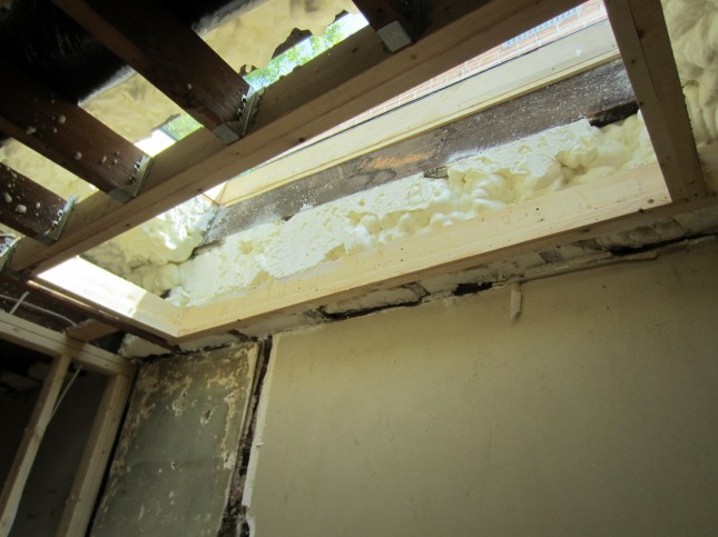
And, in the guest bedroom, looking west, where it has completely covered the in-line fan units described in this post, as well as the accompanying video:

And looking east:

We’ve also installed foam insulation in the joists below the overhang in back that was created by the master bedroom bumpout:

Next up: batt insulation installation blog publication.

 
2 Comments

Posted by on May 19, 2012 in Insulation


A Final Look at House Infrastructure – First Floor

At the front of the house, there’s a gang of switches, and the electricians had to demo the plaster in this area to run the new wires. All of the casing around the doors and windows has been removed, as well . . .

Our powder room wall is more infrastructure pipes and wires than it is framing . . .

To the south of the powder room, the pantry walls house plumbing and electrical, including bundles of electrical wires running up the end of the new wall from the electrical panel below to supply the second floor.

Rough-ins for the south end of the kitchen:

And electrical, gas, and the hood vent to support elements on the west wall of the kitchen:

The kitchen walls also house hydronic infrastructure elements. Here, the red, radiator supply and return lines for the master bedroom travel up the kitchen bump-out wall:

You can see a 360-degree view of the first floor (in the gloom resulting from boarded-up front windows) at:

http://youtu.be/qqFarZgN1UU

As with the second-floor walkthrough videos, this one does nothing but reinforce the exceedingly geeky interest we have in the renovation details. However, it does provide an interesting view of the house infrastructure elements in a different context.

 
2 Comments

Posted by on May 15, 2012 in AC and Hydronics, Electrical, Plumbing


A Final Look at House Infrastructure – Second Floor

The exposed-infrastructure stage of home renovation is drawing rapidly to a close. Insulation and drywalling activities are looming (they’re actually already here, it’s just that our posts are woefully behind), and it’s time to take a final look at the exposed house elements before they’re forever entombed.

On the second floor, there’s a mess of plumbing, electrical, and mechanical elements in the utility closet between the hallway and the master bedroom. The placement of the air handler on the top floor (consistent with the pre-reno house) helps in AC distribution and minimizes the distance between this component and the compressor directly above it on the roof.

The utility closet also will house stacked, front-loading washer and dryer. The blue spot on the floor in the photo above is one end of the emergency drain line that exits directly from the side of the house in case the washer has an issue. Rough-in electrical and plumbing occupy the south wall of the utility closet for the washer and dryer.

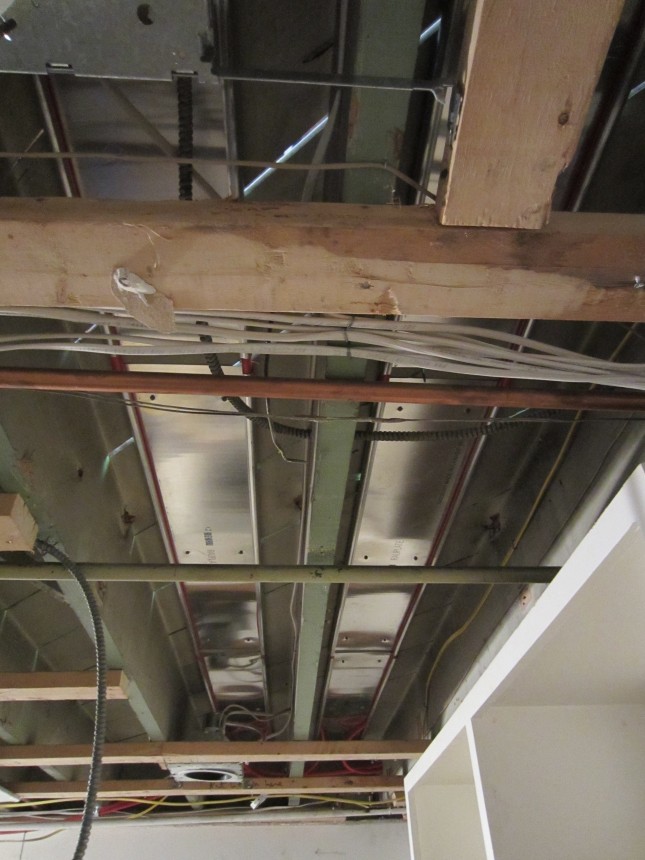
The wall between the two upstairs bathrooms house all of the plumbing supply and drain lines and electrical rough-ins. All of the extra wiring supports subsequent pendant lights in the master bath and sconce lights in the guest bath.

The plumbing rough-in for the two bathrooms is identical: supply lines for flow control valves and fixtures for shower heads and hand-held showers and a thermostatic controller that supports both.

Lots of electrical rough-in elements surround the bathroom framing:

In-line fans mounted above the guest room rafters support both bathrooms. Because of the floor-to-ceiling glass doors on the showers, we need to vent moist air, and these remote fans take care of this nicely. The GC wanted to install routine bathroom ceiling fans, but this approach supported both showers and bathrooms, and were super efficient, so we went with this approach, spec’d by our first architect.

A subsequent picture of the fans appears below, after the insulated vent lines have been attached.

Electrical rough-in also had to contend with solid brick exterior walls in much of the house. The result was a collection of new pockets in the brick to accommodate electrical outlets that will poke through the baseboard in the guest room, pictured below, and all over the main floor, the subject of the next post.

You can see a 360-degree view of the south side of the second floor at:

http://youtu.be/_kX8gQRT61Q

And you can see the same for the north side at:

http://youtu.be/Hbyf_XA21IY

Both links are dorky as hell, but highly informative!

 
Leave a comment

Posted by on May 15, 2012 in AC and Hydronics, Electrical, Plumbing


Kitchen Design Crosses the Finish Line

Starting last fall, and throughout the renovation activities to date, we’ve been working with a kitchen designer and our architect(s) to refine the overall design of the kichen initially outlined in our renovation plans. This process continued moving inexorably towards a final design, but ongoing changes–both major updates and minor tweaks–resulted in multiple delays in placing the order for the cabinetry. One of our friends warned us that the kitchen cabinets would be the longest lead-time item in our project and he was certainly correct.

As a result of our delay in ordering the cabinetry, which has a 10-week leadtime, our move-in date now looks like early August instead of mid-July. We’re working with our kitchen designer to try to accellerate this by moving our order further up in the cabinet-maker’s queue, but it’s a crap shoot, and we may not be back in the house when we wanted to be.

The original floor plan for the kitchen is shown in the before-and-after sketch below. As indicated in the sketch, much of the working kitchen area (sink, oven/stove, and refrigerator) would exploit the new, 5′ x 8′ bumpout at the rear of the house:

Additional detail on the floor plan for the kitchen is in a subsequent sketch in the master plans. A couple of changes from the sketch above are evident here.

  • The kitchen sink, originally centered on the west window, would be centered between the two windows, which is what we wanted to do originally, but could not figure out how, due to the sink size and cabinet size. Our kitchen designer effectively addressed this.
  • The wet bar trough sink, originally placed on the north end of the wet bar counter in an east-west orientation, is now placed on the south end of the counter at the back, in a north-south orientation. There are several reasons for this change. First, we moved the wine refrigerator under the wet bar to the north side of the wet bar to avoid having a thin panel enclose it (it’s now optimally situated between the powder room wall and wet bar cabinetry). The sink can’t be located on top of this appliance, so it swapped places. Second, we wanted to maintain as much functional use of the counter space as possible, so we moved the sink to the rear of the counter.
  • Although not technically part of the kitchen, we also moved the sink in the powder room by the time of this sketch, since it originally was located against the brick exterior wall, and we didn’t want more pipes exposed than was absolutely necessary.

One other item that still appears on the kitchen floor plan above that has since changed (and is not necessarily evident from the elevations below), is a second faucet-type item that appears next to the wet bar faucet (labeled J and K, above). As designed, this was to be a much-anticipated beer tap for kegs stored below in the basement in the repurposed refrigerator from our old kitchen. Unfortunately, at some point in April, we realized that the length of the beer line from the basement to the tap was too long to be air cooled and the other alternative–glycol cooling, used in commercial applications–was way too expensive. Half of our household became despondent and almost apoplectic with grief over the loss of this key renovation design element. The other half just couldn’t stop grinning gleefully about the death of an idea that had been objected to from the start.

The situation was not at all unlike the reactions of Ralphie’s parents upon the demise of the fishnet stocking-clad leg lamp (“a major award!” in “A Christmas Story”). One party loudly bemoaning the loss, the other quietly smirking in satisfaction.

Enough on the floor plans and the sad death of one guy’s simple dream of having draft beer at his wet bar. Moving on to the kitchen elevation drawings detailing what, at long last, we’ve decided to do here.

First up is the west wall of the kitchen, where most of the cabinetry and several key appliances will reside. As originally designed, our plans called for a 30″ stove top nestled within the counter, and a separate wall oven below, ensconced in cabinetry. We really dig the look of these components as integrated, built-in pieces of the kitchen.

However, as we looked at different appliance options for these components our eyes would continually wander, lustfully, to the big-ass 36″ stainless steel ranges. We tried to maintain fidelity to our original choice, and tear our eyes away, but we ultimately succombed to our desires and redesigned this area of the kitchen around a 36″ stainless steel behemoth. We both are passionate about cooking, so we’re rationalizing this deviation from the plan by planning for the multicourse meals we’ll be making after we move back in again, with multiple pots and pans on the 6-burner stove.

Other components on the west wall include a counter-depth refrigerator (the dimensions in the elevation are correct, but the actual unit will have equal-sized French doors on top and a freezer drawer below). To the right of the refrigerator, located in the larger of the two cabinets, is a microwave. The door in front has a power assist, which is pretty slick – you just touch it and it moves out and up.

The dining peninsula/huge kitchen work space is the last item to the right. The bulkhead above helps define this area, as does the large, single piece of cabinetry above the table/counter on the west wall.

The cabinets themselves will be frameless with maple doors in a “praline” stain to contrast with the dark walnut floors below, and the white quartz countertops above. A photo of the sample we’ve been obsessively carrying around with us is below:

We considered doing painted cabinets in a taupe/putty color, which would have looked awesome with the chocolate floors and white quartz counter tops, but the old kitchen had painted cabinets, and we’ve seen the effects of use on corners and around the pulls and knobs, so we wanted something that would withstand abuse a little better. We chose maple because of the minimal grain; the stain gives the wood a nice neutral quality. The wide rails and stiles of the cabinet doors, shown in the sample above, gives the cabinets a “Shaker-style-on-steroids” look that we like, and will also be consistent with the clean lines of the rails and stiles of the passage doors throughout the house.

On the south wall will reside the other components of the working aspect of the kitchen (versus the eating aspect at the peninsula and the drinking and storage aspect at the wet bar / pantry area to the east). In the elevation below, the sink is centered between the two kitchen windows (the faucet will be, as well, even though this drawing does not show this). To the right is a panelized dishwasher (one of the minor changes we made during our continual rescrubs of the kitchen design was to replace a full-sized panel with a panel and drawer front to make the dishwasher further blend in with the other cabinets). To the right of the sink cabinet is the trash drawer, with two bins (one of which will now receive way more beer bottles than planned, due to the demise of the beer tap dream . . .).

The wet bar and pantry area is along the east wall, essentially where the old kitchen was. As noted above, the wet bar will include a wine refrigerator on the left and a sink on the right. The wall cabinets above, where wine glasses and other glassware will be stored, will help define this space as different than the rest of the kitchen, since they’ll have glass doors.

The wet bar isn’t just for der drinking; our espresso maker and kick-ass aerocino machine will be located here, as well, and coffee cups will be stored above with the glassware. (We’re still going back and forth about whether we should have frosted glass installed here, instead of clear glass, for this reason. Our architect thinks the clear glass would be better and that we shouldn’t worry about the coffee mugs. Let us know if you have an opinion one way or another.)

One of the last items we changed in the kitchen design (that cost us another few days in delays, but was totally worth it), was to add a drawer to the wet bar area. Up until a week ago, the design simply called for double cabinet doors under the counter. We realized that there was no where to store cork screws, bottle openers, tooth picks, etc., and made the change before it was too late. The drawer itself will be shallow (9″) because of the trough sink at the back, but there will be plenty of room for what we’ll use it for.

The cabinets to the right provide a pantry area. The right half of the southern-most cabinet will have full length access to store brooms, etc., and the cabinet doors there will be joined to open as one.

The end of the kitchen cabinetry at the bulkhead will be defined by a built-in bookcase of the same maple. The cabinet below the peninsula (and behind the bookcase) is difficult to access, and so became the perfect location for the subwoofer for the living room’s AV system. The space already has been wired by our AV consultants, and by the GC’s electrician to accommodate this audio component. Rather than a wood door, we’ll install a metal grill to the front of this cabinet (facing the length of the dining peninsula).

The bookcase at the end of the kitchen will, in the parlance of our first architect, “talk to” a twin bookcase across the living room. As a result, the bookcase and knee wall cabinetry at the front of the house will be identical to the cabinetry in the kitchen. These bookcase elements will be both functional and are critical design elements that define the living room space. A floor plan view of the entry knee wall and bookcase is below.

The elevation drawing below shows the north bookcase and knee wall cabinetry, in the middle of which will reside a gas fireplace.

 
4 Comments

Posted by on May 13, 2012 in Design, Kitchen


Basement Utilities Reach Critical Mass

One of the advantages of our basement demolition and excavation efforts was to clear out decades of plumbing, hydronics, and electrical (especially electrical – we had three generations of technology down there, from some original knob-and-tube, to wire conduit, to Romex), and start anew with a basement utility hub that wouldn’t eventually burn down the house.

The additional benefit of the excavation of the southeast crawlspace, specifically, was to allow the boiler (which would supply hot water to the radiators and heated floors), the hot water heater, and the electrical panel to be consolidated in one area of the basement. This would allow maximum utilization of the remaining area. This crawlspace area was barely usable in the pre-reno house. Some pics of the basement before are provided below.

Here’s the old boiler and hot water heater, located on the west side of the basement (really, the only place they could be, due to the limitations in this area):

This is an even better picture of the mayhem that lay dormant in our basement. Looking through the doorway, you’ll see the old electrical panel, located in the quasi-exterior area in the basement. Note the crawlspace area between the door and the panel – previously of limited use, this will be the home of the new home utility hub. The plumbing stack in front will remain where it is (as seen in https://wolfestreetproject.com/2012/04/09/insane-in-the-main-drain/).

Regarding the tangle of old wiring, plumbing, and hydronic elements in the old house, check out this action, which includes hydronic lines to nowhere that were capped off when radiator locations changed during previous renovations:

All of this came to a satisfying end with the demo work. Our contract with the GC specified that everything down here would be eliminated and reinstalled and replumbed and rewired anew . . .

After demo and reconstruction of the expanded basement (https://wolfestreetproject.com/2012/03/15/slab-happy/), the first step of our new power plant installation was arrival of the boiler and hot water heater. The boxes obviously contain these items; the equipment already mounted to the block wall is the manifold for the hydronic lines, which we’ll see later:

These elements will actually be located in the space that previously was occupied by crawlspace, so, bonus in space utilization, eh?

To the right of the boiler and water heater will reside the “heavied-up” electrical panel (from 100 to 200 amps) to support more electrical. At this point, it’s just the termini of a bunch of electrical cables.

Here’s a photo of the water heater and boiler after initial installation. There’s a lot more to go before this area is complete, including installation of the electrical panel, which is still AWOL at this point. The grey canister is the new expansion tank, which previously was a large, green drum about 5x the size that hung from the joists above the work bench. The old tank needed to be drained periodically, and so we’d have to screw a hose onto it and run the hose across the basement to the utility sink. The worst part was that there was no venting on the drum, so the water that had built up would drain for hours. The new expansion tank has a rubber bladder inside that contracts when water needs to escape from the hydronic lines, then expands to expel it back again when the expansion need abates. No muss, no fuss.

In the photo below, the electrical panel has been installed, as well as additional electrical lines (and the underfloor heating at the back of the house, which we’ll see in more detail). Jim, the lead for the mechanical sub, is doing some install work down here the day the picture was taken. (They did a spectacular job with installation of both the hydronic infrastructure and the AC components.)

Another new development at this stage is installation of the electrical panel (sans connections).

This is what’s lurking behind there – a manifold to route hot water from the boiler to three zones in the house. At this point, there’s only a few lines coming off it, but it’s going to get really crowded.

The three climate zones in the house are:

  • The second floor, heated by salvaged radiators in each of the two bedrooms, as well as under-floor electrical heat in the two bathrooms,
  • The first floor, heated by under-floor hydronic heat in the vestibule and kitchen, and by two small (really, really small) radiators in the powder room and the area at the top of the stairs the basement, and
  • The basement, heated by radiators in the office area and in the unfinished area.

In addition to controlling the radiant heat (as well as the AC) via thermostats on each floor, there are failsafe controls directly on the trunk lines for hot water heading into each zone. These three brass, manual controls can be seen on top of the copper pipes in front of the PVC drain line and above the expansion tank.

The red tubing feed two types of radiant head elements – radiators (before which they are connected to copper pipes) and under-floor heating. In the photo below, you can see some of this latter heating approach.

Here’s a view of the actual heating elements. Insulation beneath the radiant elements will be installed later, with a reflective side against the metal plates.

Unlike the new basement area, where we had brand new, virgin framing to work with, the under-floor heating in the front of the house had to be run through existing space. The guys had to rip out drywall and install the radiant plates and hydronic lines above the built-ins, which we’re retaining:

This is pretty much the apex of hydronic lines. The red ones heading up in the photo are supply and return lines for the master bedroom radiator and under-floor heating in the kitchen.

Late in the infrastructure game, the gas lines were finally run. We had to upgrade our meter to a high-pressure line to accommodate the additional appliances. Gas will be required in the renovated house for the following:

  • Hot water heater
  • Boiler
  • Dryer in the basement
  • Stove
  • First-floor fireplace
  • Master bedroom fireplace (future)

Similar to the manifold approach to distribute hot water for radiant heat, a manifold was installed to distribute gas to the appliances throughout the house:

The yellow gas lines shortly thereafter began to infiltrate the basement. Here’s a shot after the lines were run off the manifold. In addition to the new lines, insulation in the first-floor joist bays has been complete at this point. The area’s dense with equipment, electrical lines, hydronic lines, and gas lines, now that the basement utilities have reached critical mass, but we’re happy it’s all in once place, compartmentalized from the rest of the newly excavated area (which will allow for storage of more bikes, of course . . .).

 
Leave a comment

Posted by on May 7, 2012 in AC and Hydronics


The Back Gets a Trim (and Some Siding)

Now that the windows were in, we could move forward with cladding the exterior in the back (nothing’s being changed in the front of the house).

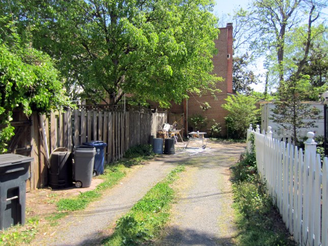
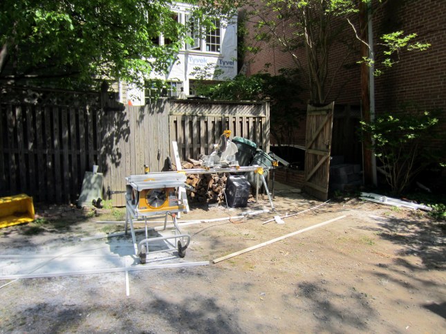
The guys set up shop for cutting trim and siding out in the alley:

For the next few days, the back of the house would be clad first in Azek trim, then with HardiePlank siding. Azek trim looks like white wood, but it’s actually PVC, so it’s pretty much bombproof, in terms of resisting the elements. HardiePlank clapboard siding is a mix of concrete and wood, so we should have a stable shell on the house for a few decades.

The first thing to be installed (after the rockin’ coped trim in the corner) was Azek trim on the bottom of the house. Dave recommended going with a wide, beefy look, and we agreed (it turned out great, as you’ll see). Right above the trim is a thin, metal drip edge, above which will be installed the clapboard siding.

One of the other design issues was how to address the narrow space between the window trim and the corner trim at the eastern edge of the new bumpout. Dave; Harry Braswell, the GC owner; and others consider the situation, below.

The solution we arrived at was to fill the narrow space between window trim and corner trim with a recessed piece of Azek at the same profile as the siding to come. However, there was some confusion in execution, as seen here, which subsequently was corrected.
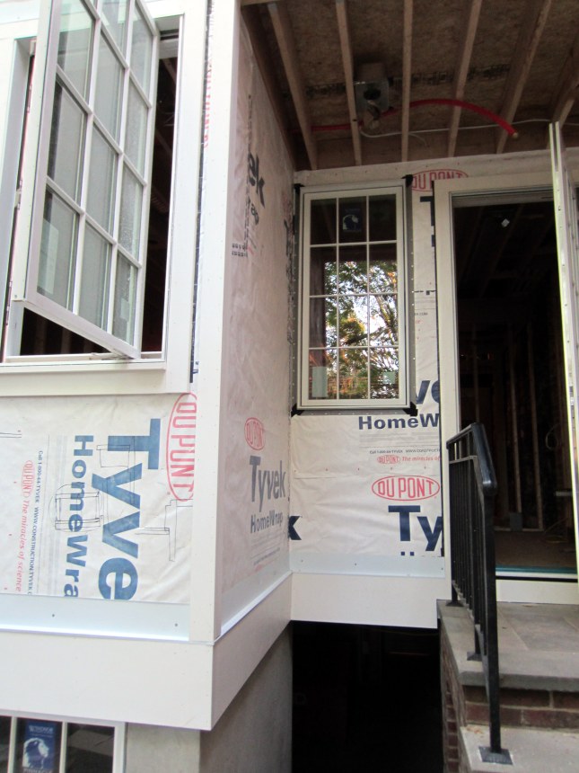
An update appears below.

Quite a bit more progress has been made at the time of this shot. Siding has now been installed on most of the back of the house. It’s pretty much the color that it will be painted, even though it’s just primed at this point. The trim has not yet been installed between the window and corner, though.

The end result turned out great. Although still not painted at this stage, the clad back of the house, with the bumpout and overhang over the kitchen door, worked out great. The pillar to the right also has been completely trimmed out, and the base of the pillar fits perfectly on the step. Finally, the other element to be seen is the vent for the new range, which bursts out of the left side of the house like an unwelcome carbuncle, but we need to address both function and form . . .

The only thing missing at this point is siding in the area under the overhang. The window to the left of the door in that area was supposed to be hinged left (so it opened away from the door and so the opened window would be positioned next to the edge of the house, rather than in the middle of this space), but the order was incorrect. So, we’re waiting for the replacement with the correct-sided hinge before this area gets completed.

 
4 Comments

Posted by on May 5, 2012 in Exterior